How to Use the RC Filter Calculator
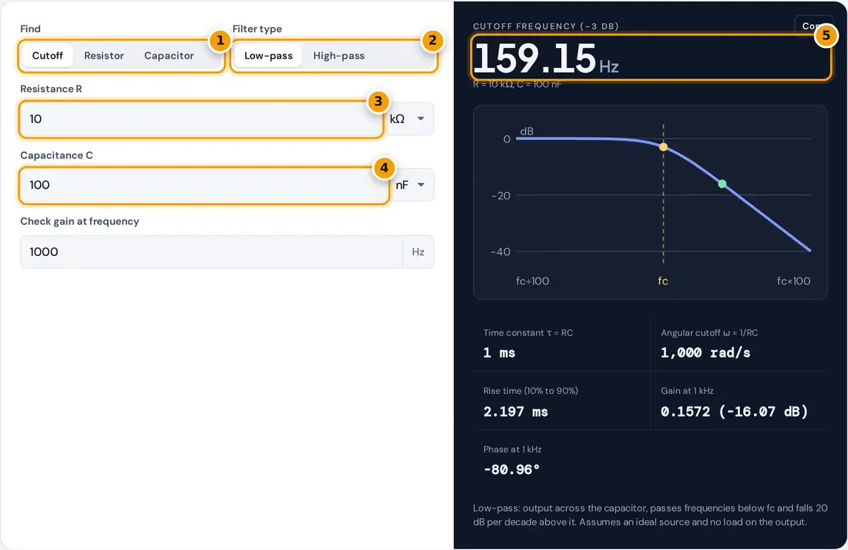
- Choose what to find: the cutoff frequency, the resistor or the capacitor.
- Choose low-pass or high-pass.
- Enter the resistance and pick Ω, kΩ or MΩ.
- Enter the capacitance and pick pF, nF or µF.
- Read the cutoff frequency, then the time constant, gain and phase.
Choose what you want to find. Cutoff takes a resistor and a capacitor and returns the cutoff frequency. Resistor and Capacitor work backward from a target cutoff frequency and the other component, and also list the nearest E12 and E24 standard values with the cutoff each one gives. Pick low-pass or high-pass, and enter a frequency to check the gain and phase there.
The Bode plot shows the magnitude response four decades wide, from one hundredth of the cutoff to a hundred times the cutoff. The yellow dot marks the −3 dB cutoff and the green dot marks your check frequency.
The Cutoff Frequency Formula
τ = R × C
Low-pass gain = 1 ÷ √(1 + (f ÷ fc)²), phase = −arctan(f ÷ fc)
High-pass gain = (f ÷ fc) ÷ √(1 + (f ÷ fc)²), phase = 90° − arctan(f ÷ fc)
Gain in dB = 20 × log10(gain)
At the cutoff frequency the capacitor’s reactance equals the resistance, the output falls to 1 ÷ √2 = 0.7071 of the input, which is −3.01 dB, and the phase shift is 45°. Far from the cutoff, a first-order RC filter rolls off at 20 dB per decade, or about 6 dB per octave.
Worked Example
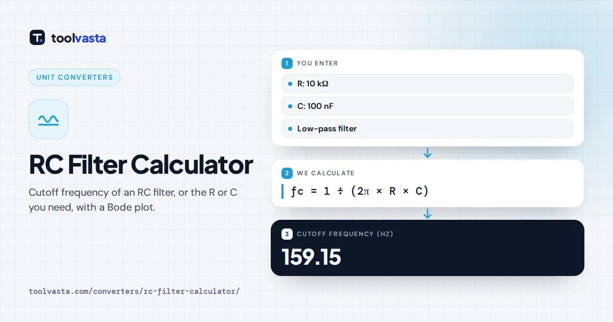
A 10 kΩ resistor and a 100 nF capacitor give τ = 10,000 × 0.0000001 = 1 ms and fc = 1 ÷ (2π × 0.001) = 159.15 Hz. As a low-pass filter, a 1 kHz signal comes through at 1 ÷ √(1 + (1,000 ÷ 159.15)²) = 0.1572 of its amplitude, which is −16.07 dB, with a phase shift of −80.96°.
To design a 1 kHz low-pass filter with a 100 nF capacitor, R = 1 ÷ (2π × 1,000 × 0.0000001) = 1.592 kΩ. The nearest E12 value is 1.5 kΩ, giving 1.061 kHz, and the nearest E24 value is 1.6 kΩ, giving 994.7 Hz.
E12 and E24 Standard Values
| Series | Values in each decade | Typical tolerance |
|---|---|---|
| E12 | 10, 12, 15, 18, 22, 27, 33, 39, 47, 56, 68, 82 | ±10% |
| E24 | 10, 11, 12, 13, 15, 16, 18, 20, 22, 24, 27, 30, 33, 36, 39, 43, 47, 51, 56, 62, 68, 75, 82, 91 | ±5% |
The values repeat in every decade, so 4.7 kΩ, 47 kΩ and 470 nF all come from the same series. These preferred number series are defined in the international standard IEC 60063. Capacitors are most often stocked in E6 or E12 values, so it is usually easier to pick a standard capacitor first and then solve for the resistor.
Common Uses of RC Filters
Low-pass RC filters smooth a pulse width modulated (PWM) signal into an analog voltage, remove high frequency noise before an analog to digital converter, and slow down switch contacts so a microcontroller reads one clean press. High-pass RC filters block DC while passing audio, which is why a coupling capacitor sits between amplifier stages, and they also remove slow drift from sensor signals. Choose the cutoff well away from the signals you want to keep: a factor of ten gives a gain error under 1%.
Design Tips
- Keep the source impedance low and the load impedance high compared with R. A load connected to the output acts in parallel with the capacitor or resistor and shifts the cutoff.
- Ceramic capacitors with X7R or similar dielectrics can lose much of their capacitance with DC bias and temperature. Use C0G (NP0) or film capacitors when the cutoff must be accurate.
- For a steeper roll-off, cascade stages with a buffer between them, or use an active filter design. Two identical passive RC stages connected directly do not give a clean 40 dB per decade response at the same cutoff.
- For switch debouncing and power supply filtering, the time constant τ is often more useful than the cutoff: a capacitor charges to about 63% in one τ and 99% in five.
Frequently asked questions
What is the formula for an RC filter cutoff frequency?
The cutoff frequency is 1 divided by 2π times R times C, with R in ohms and C in farads. A 10 kΩ resistor and a 100 nF capacitor give 1 divided by 2π times 0.001, which is 159.15 Hz.
What happens at the cutoff frequency?
At the cutoff frequency the output is 70.71% of the input amplitude, a drop of about 3 dB, and the phase shift is 45 degrees. The capacitor's reactance equals the resistance at this point.
How do I choose R and C for a 1 kHz filter?
Pick a convenient standard capacitor first, such as 100 nF, then solve R equals 1 divided by 2π times 1,000 times C. That gives 1.592 kΩ, so a 1.6 kΩ E24 resistor lands close to 1 kHz.
What is the difference between low-pass and high-pass RC filters?
Both use the same R and C and have the same cutoff frequency. A low-pass takes its output across the capacitor and passes low frequencies; a high-pass takes it across the resistor and passes high frequencies.
How fast does an RC filter roll off?
A single RC stage is a first-order filter, so beyond the cutoff its response falls by 20 dB per decade, which is about 6 dB per octave. At ten times the cutoff a low-pass passes about one tenth of the signal.
What is the RC time constant?
The time constant τ equals R times C, in seconds. In one time constant a capacitor charges to about 63% of the applied voltage through the resistor, and after five time constants it is over 99% charged.